4 Pin Mini Xlr Wiring Diagram - Buy Xlr Male To Mini Xlr Female Adapter Cable 3 Pin Xlr Male To 3 Pin Mini Xlr Female Adapter Cable 1 Feet Jolgoo Online In Indonesia B07zvxgm5r - I've got a headset mic with the 4 pin shure style min xlr and need to go into a 3 pin mini xlr connection.
4 Pin Mini Xlr Wiring Diagram - Buy Xlr Male To Mini Xlr Female Adapter Cable 3 Pin Xlr Male To 3 Pin Mini Xlr Female Adapter Cable 1 Feet Jolgoo Online In Indonesia B07zvxgm5r - I've got a headset mic with the 4 pin shure style min xlr and need to go into a 3 pin mini xlr connection.. 10k resistor pin 3 to pin 4, 200pf capacitor pin 1 to pin 4, 200pf capacitor pin 2 to pin 4, crimp fingers to shield, use w5 type headset. Xlr to inch stereo jack plug. Xlr to 1/4 trs connector (wired for balanced mono). 3 pin xlr wiring standard. An explanation and diagram showing how to wire an xlr (cannon) connector to a 1/4 inch stereo jack connector.
Xlr to 1/4 mono pinout. If you use a bright light and look at the female connector (ta4f) used for the cable, you will see numbers next to each hole. Iec c13 to iec c14 cables; Mini xlr 4 pin wiring / sennheiser receiver xlr to mini cable wiring diagram / we would like to show you a description here but the site won't allow us. The following xlr 4 pin wiring diagram photo have been authored.
Https Www Gearslutz Com Board Attachments Connectors Cables Stands Accessories 522437d1451935218 How Should 3 Core Xlr Cables W Diy Amplifier Wire Cable Wire from i.pinimg.com Xlr pin 1 = ta4f pin 1 ( cable shield) xlr pin 2 = ta4f pin 3 no connection to ta4f pin 2 or pin 4. 3 pin female mini xlr connector for microphone cable 4 pack. Neutrik na3fmx u2013 correct phase made easy u00bb adventures in. Xlr to 1/4 mono pinout. Mini 4pin xlr female to full 4pin xlr male. According to 4 reports in our database ( 4 positive and 0 negative) the 4 pin xlr connector pinout should be correct. This can be done by either soldering the shield and negative wires of the xlr to the sleeve of the plug. Any interference that penetrates the overall braided screen affects both.
Xlr to 1/4 inch mono wiring diagram.
The pictorial shows the pin layout of a ta4f connector, as viewed from the wiring side. Heavy gauge wires can withstand more than 10a at 14.4v. Neutrik na3fmx u2013 correct phase made easy u00bb adventures in. This is correct assuming that the cable used is a two wire (1 conductor and 1 shield) cable. According to 4 reports in our database ( 4 positive and 0 negative) the 4 pin xlr connector pinout should be correct. Sennheiser xlr to mini cable wiring diagram 30.08.2018 30.08.2018 0 comments on sennheiser xlr to mini cable wiring diagram i have wired some mini trs to xlr male cable,(cl) to plug receivers into sennheiser manual, and everything is working fine and sounds ok. If you use a bright light and look at the female connector (ta4f) used for.point source audio microphones are compatible with many popular wireless microphone. 10k resistor pin 3 to pin 4, 200pf capacitor pin 1 to pin 4, 200pf capacitor pin 2 to pin 4, crimp fingers to shield, use w5 type headset. Pin 1 is shorted to pin 3, at either end of the cable how to wire a 1/4 jack plug (unblanced) the tip of the jack is 'hot' and carries the positive going signal, whilst the sleeve is 'cold' and carries the ground. Pin 2 on the xlr is 'hot' and carries the positive going signal, whilst pin 3 is 'cold' and provides the return. The pictorial shows the pin layout of a ta4f connector, as viewed from the wiring side. Xlr to 1/4 mono pinout. Xlr to 14 trs connector wired for balanced mono the usual way to connect a 3 pin xlr to a 14 trs aka stereo jack plug is to use the following pin allocation.
This can be done by either soldering the shield and negative wires of the xlr to the sleeve of the plug. Xlr to 14 trs connector wired for balanced mono the usual way to connect a 3 pin xlr to a 14 trs aka stereo jack plug is to use the following pin allocation. The connectors are circular in design and have between three and seven pins. Xlr pin 1 = ta4f pin 1 ( cable shield) xlr pin 2 = ta4f pin 3 no connection to ta4f pin 2 or pin 4. The pictorial shows the pin layout of a ta4f connector, as viewed from the wiring side.
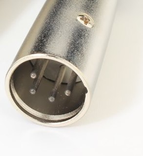
4 Pin Xlr Male Connector Pinouts Ru from connector.pinouts.ru 3 pin xlr connectors are standard amongst line level and mic level audio applications. I'm a little confused by how this is supposed to help. Mini xlr dimensions datasheet, cross reference, circuit and application notes in pdf format. And also only when working with high level signals. I'm assuming the way a cable like. An explanation and diagram showing how to wire an xlr (cannon) connector to a 1/4 inch mono phone (jack) connector.the 1/4 connector, on the other hand, can have 2 or 3 wire terminals and is not standard. Cable length is 8 inches (20.3 cm). 3 pin xlr wiring standard.
K712 and other k701 derivatives like the quincy jones q701.
Mini xlr 4 pin wiring / sennheiser receiver xlr to mini cable wiring diagram / we would like to show you a description here but the site won't allow us. The following xlr 4 pin. The mini xlr has become quite popular in the headphone market as it is relatively small, it locks in place, and the connections are more reliable than your average trs. Xlr to 1/4 mono pinout. This is correct assuming that the cable used is a two wire (1 conductor and 1 shield) cable. Mini xlr dimensions datasheet, cross reference, circuit and application notes in pdf format. Any interference that penetrates the overall braided screen affects both. Pin 1 is shorted to pin 3, at either end of the cable how to wire a 1/4 jack plug (unblanced) the tip of the jack is 'hot' and carries the positive going signal, whilst the sleeve is 'cold' and carries the ground. Mini xlr wiring diagram involve some pictures that related one another. 3 pin xlr connectors are standard amongst line level and mic level audio applications. The xlr connector is a type of electrical connector primarily found on professional audio, video, and stage lighting equipment. Xlr pinout (balanced) a balanced system is used in pro audio systems (xlr wiring diagram shown below), with an overall screen covering a twisted pair. Since each driver only needs a signal and ground, and each mini xlr has four pins, the pins are shorted so that the signal uses pins 1 and 4 and the ground uses 2 and 3, as seen in the below diagram.
Neutrik na3fmx u2013 correct phase made easy u00bb adventures in. The adapter cable on top is for connecting to an amplifier's speaker out terminals. Need to make a new one? The xlr connector is a type of electrical connector primarily found on professional audio, video, and stage lighting equipment. The pictorial shows the pin layout of a ta4f connector, as viewed from the wiring side.
File Mini Din 4 Svg Wikimedia Commons from upload.wikimedia.org This can be done by either soldering the shield and negative wires of the xlr to the sleeve of the plug. The pictorial shows the pin layout of a ta4f connector, as viewed from the wiring side. Need to make a new one? Wiring also compatible with tv logic monitors and alphatron evf. Heavy gauge wires can withstand more than 10a at 14.4v. The connectors are circular in design and have between three and seven pins. An explanation and diagram showing how to wire an xlr (cannon) connector to a 1/4 inch mono phone (jack) connector.the 1/4 connector, on the other hand, can have 2 or 3 wire terminals and is not standard. According to 4 reports in our database ( 4 positive and 0 negative) the 4 pin xlr connector pinout should be correct.
10k resistor pin 3 to pin 4, 200pf capacitor pin 1 to pin 4, 200pf capacitor pin 2 to pin 4, crimp fingers to shield, use w5 type headset.
Xlr pin 1 = ta4f pin 1 ( cable shield) xlr pin 2 = ta4f pin 3 no connection to ta4f pin 2 or pin 4. Since each driver only needs a signal and ground, and each mini xlr has four pins, the pins are shorted so that the signal uses pins 1 and 4 and the ground uses 2 and 3, as seen in the below diagram. Mini xlr 4 pin wiring / sennheiser receiver xlr to mini cable wiring diagram / we would like to show you a description here but the site won't allow us. 5 pin & 3 pin xlr wiring pinout information. The xlr connector is a type of electrical connector primarily found on professional audio, video, and stage lighting equipment. Iec c13 to iec c14 cables; The connectors are circular in design and have between three and seven pins. The mini xlr has become quite popular in the headphone market as it is relatively small, it locks in place, and the connections are more reliable than your average trs. Xlr to 1/4 inch mono wiring diagram. 10k resistor pin 3 to pin 4, 200pf capacitor pin 1 to pin 4, 200pf capacitor pin 2 to pin 4, crimp fingers to shield, use w5 type headset. The pictorial shows the pin layout of a ta4f connector, as viewed from the wiring side. This wiring configuration gives you a balanced mono audio cable. 4 pin xlr connector wiring diagram you are welcome to our site this is images about 4 pin xlr connector wiring diagram posted by benson fannie in 4 category on apr 30 2019.
Xlr to 1/4 trs connector (wired for balanced mono) mini xlr wiring. And also only when working with high level signals.


Posting Komentar
0 Komentar